How Do Laboratory Condensers Optimize Heat Transfer and Chemical Separation in Industrial Scale Operations?
Vapor condensation within a closed chemical apparatus requires controlled heat extraction across a conductive boundary layer. Laboratory Condensers serve as the primary heat exchanger in organic synthesis, distillation, and reflux systems, converting gaseous phase reactants and solvents back into liquid state through contact with chilled inner surfaces. The thermodynamic performance of these instruments relies on maximizing the surface area available for vapor contact while managing fluid velocity and minimizing vapor resistance. When hot vapor enters the internal chamber of a condenser, it encounters a cooler glass wall maintained by continuous fluid circulation in an outer jacket or internal coil. As latent heat transfers from the vapor to the liquid coolant, condensate droplets nucleate on the wall, forming a thin liquid film that flows downward under gravitational force into a collection vessel or back into the primary reaction flask.
The rate of heat transfer across the glass boundary is influenced by wall thickness, the thermal conductivity of borosilicate glass, and the fluid flow characteristics of both the vapor and the coolant. Liquid coolant must enter the lowest inlet port of the condenser jacket and exit through the upper outlet port. This countercurrent configuration maintains the maximum temperature differential between the rising vapor and the cooling medium throughout the entire length of the apparatus, preventing thermal equilibrium from occurring near the vapor entry point. Maintaining an optimized cooling gradient prevents volatile organic compounds from escaping into the exhaust or vacuum system, maximizing recovery efficiency and preserving atmospheric safety within chemical processing facilities.
Thermal Dynamics and Surface Area Geometry in Chemical Vapor Condensation
The physical design of the internal condensation channel dictates the turbulence and contact time of vapor molecules against the chilled boundary. Simple straight tube designs offer low vapor flow resistance, which is suitable for simple distillation where rapid fluid movement is required without fluid holdup. Complex internal configurations such as coiled tubes or bulb chains disrupt laminar vapor flow, creating localized turbulence that forces a higher percentage of gas molecules to contact the cold glass boundary. This mechanical disruption significantly increases the effective heat transfer coefficient without increasing the overall vertical footprint of the glass assembly.
Vapor loading capacity is another critical factor in preventing system flooding and pressure spikes during high volume boiling. If vapor enters the condenser at a rate exceeding the heat extraction capacity of the cooling surface, condensed liquid cannot drain efficiently against the upward force of the incoming steam. This phenomenon, known as column flooding, leads to dangerous pressure build up, loss of fractionating purity, and potential thermal shock to the glass joints. Chemical engineers and laboratory managers must evaluate vapor velocity, boiling point ranges, and coolant temperature differentials to match specific operational scale with the appropriate internal geometry of Laboratory Condensers.
Architectural Variations of Glass Condensers for Reflux and Distillation Systems
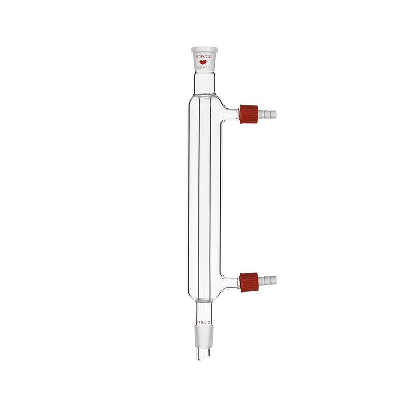
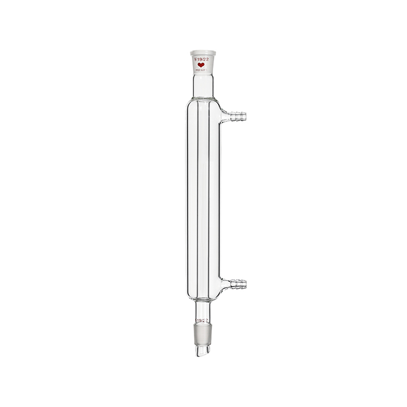
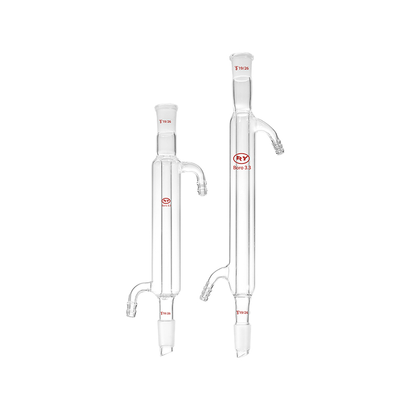
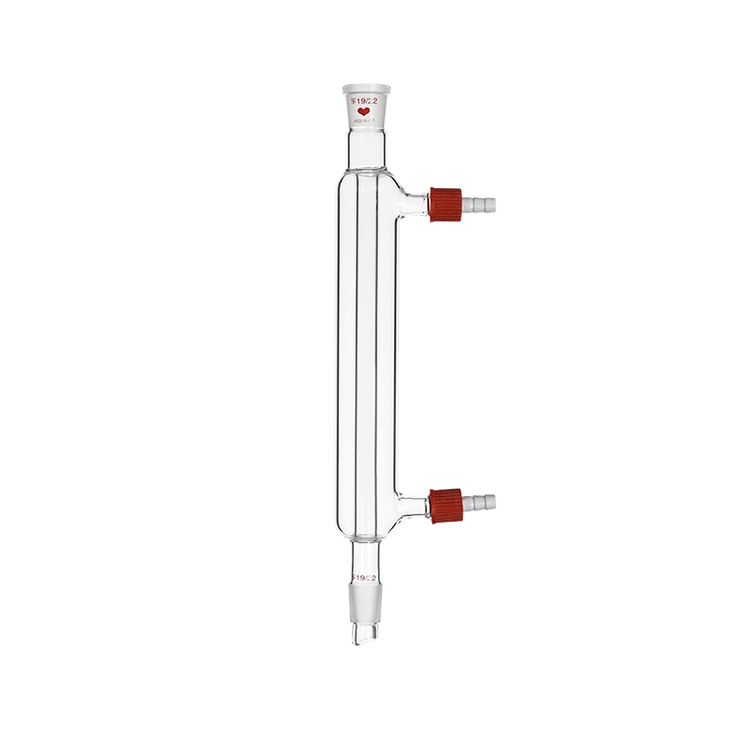
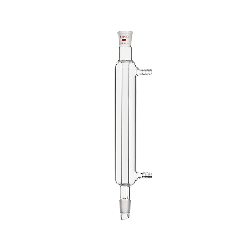
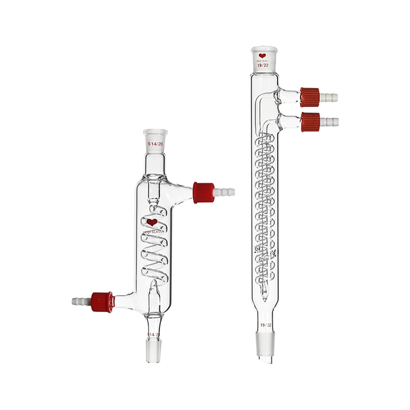
Different chemical processes demand specific architectural variations in glass condenser design. The Liebig condenser represents the classic straight tube jacketed design, providing a straightforward pathway for non volatile distillates and simple solvent recovery where moderate cooling rates are sufficient. Its linear structure facilitates easy cleaning and minimal liquid retention, making it a reliable standard for basic batch distillation setups. However, when handling highly volatile solvents or conducting reflux operations requiring long reaction times, more advanced surface geometries are required to prevent solvent loss.
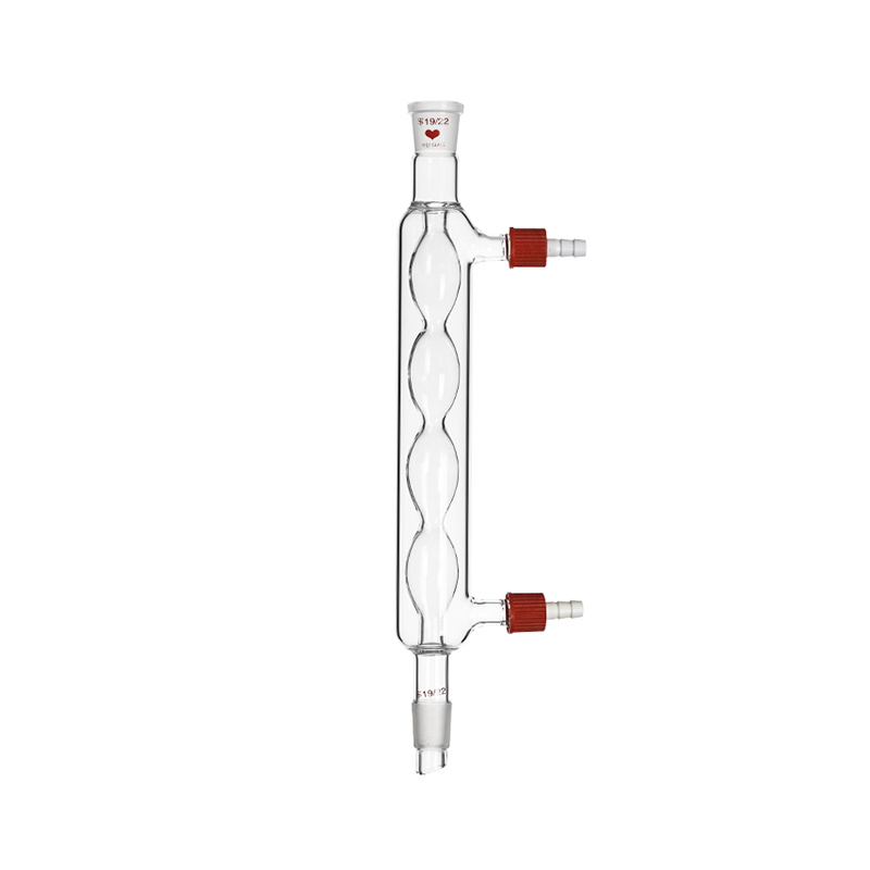
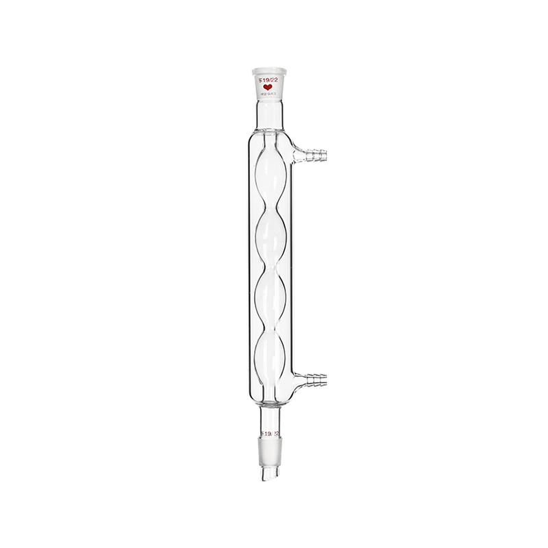
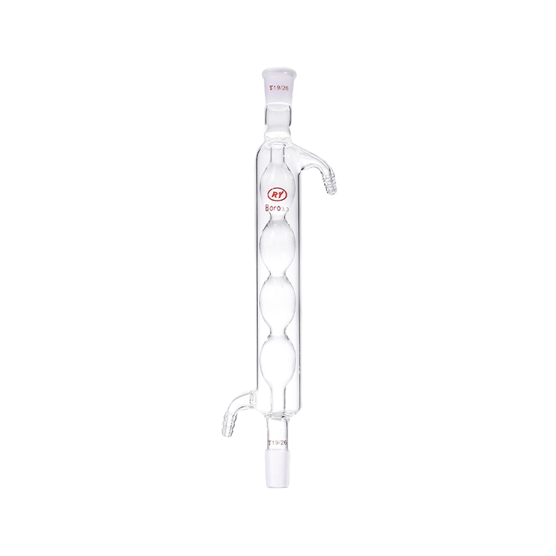
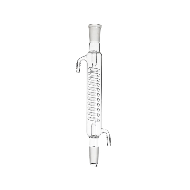
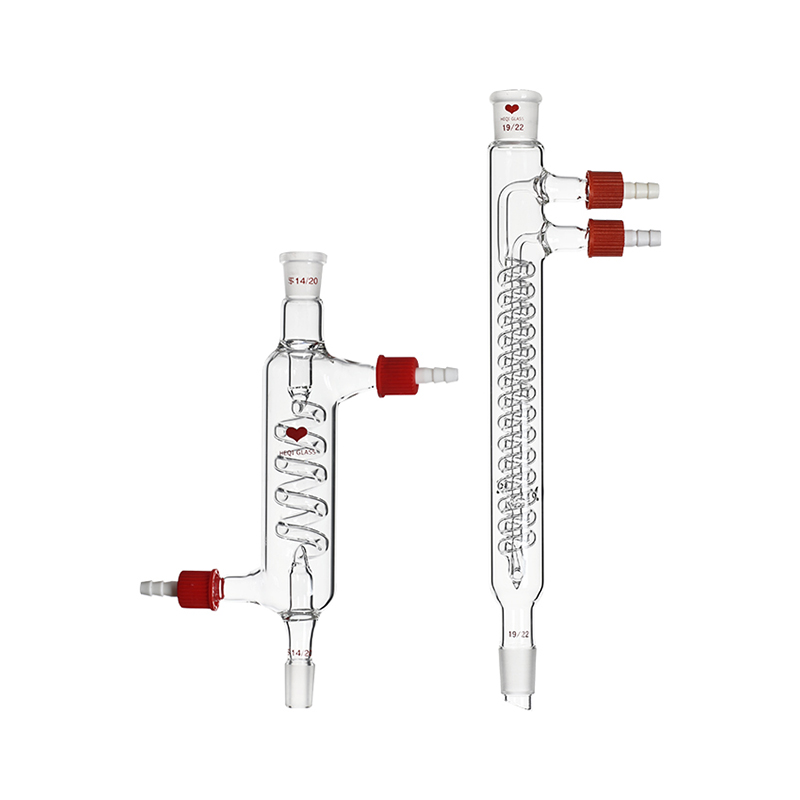
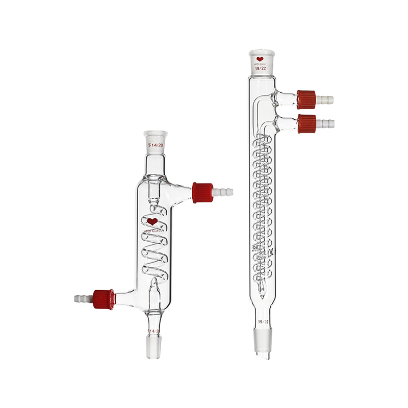
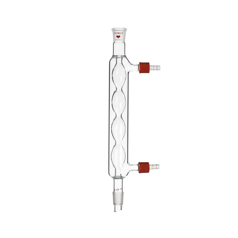
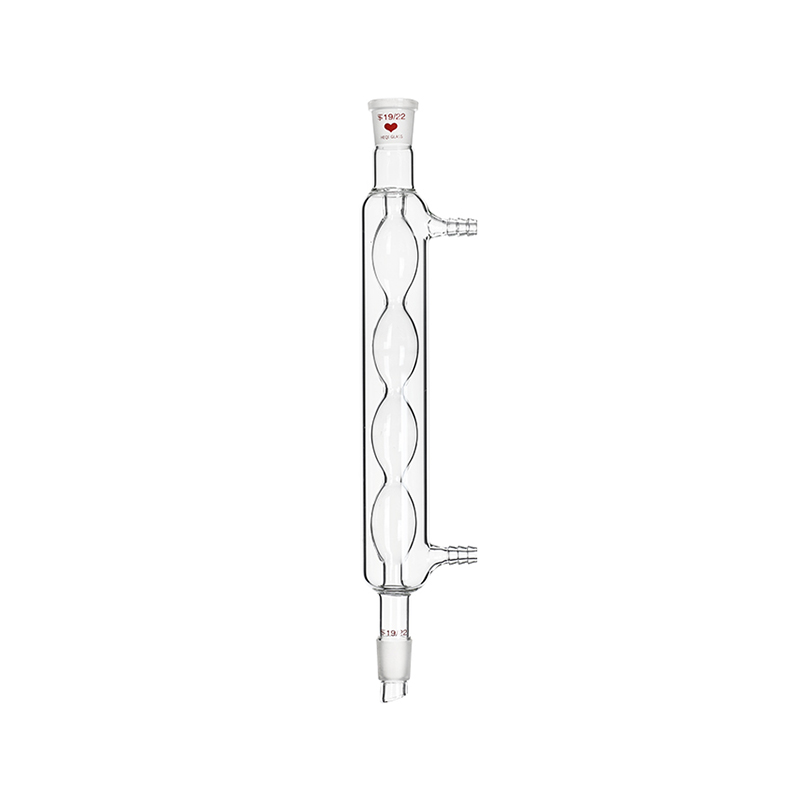
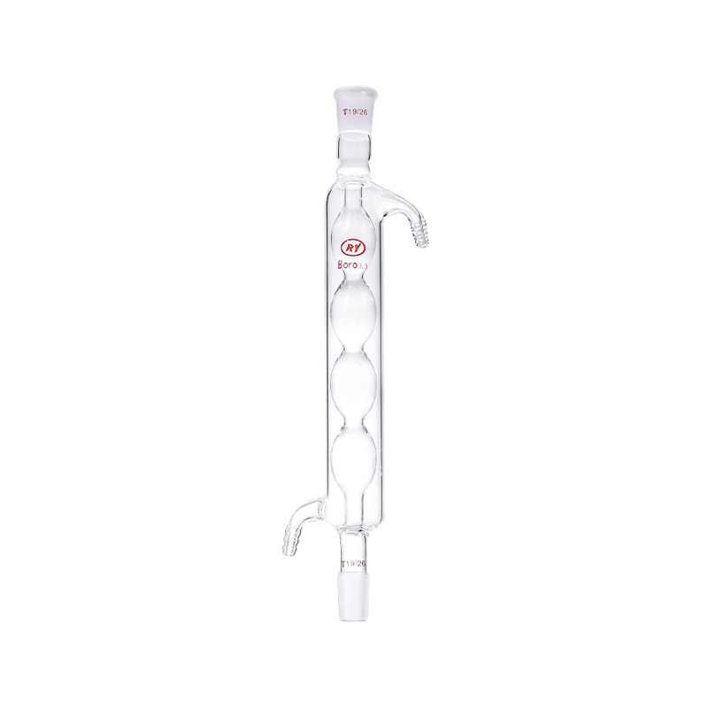
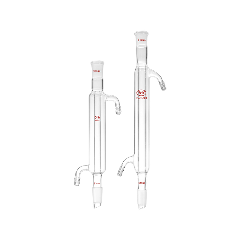
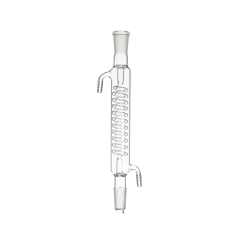
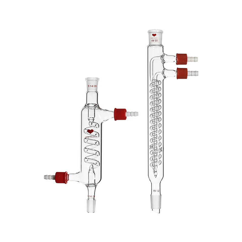
The Allihn condenser incorporates a series of internal glass bulbs that expand the available surface area while creating gentle vapor expansion chambers. This design is widely utilized for reflux applications where the liquid condensate continuously returns to the boiling flask. For processes demanding maximum heat exchange efficiency within a compact space, the Graham condenser utilizes an internal spiral coil through which vapor travels, surrounded by circulating coolant in the outer jacket. Conversely, the Dimroth condenser features an internal cooling coil through which the coolant flows, while the vapor moves through the outer jacket chamber. The Dimroth configuration is particularly effective for high throughput reflux because condensate forms on the outer surface of the internal coil, dripping directly from the center of the apparatus without bridging across the outer walls or obstructing incoming vapor.
Manufacturing Excellence from an Established Laboratory Condensers Factory
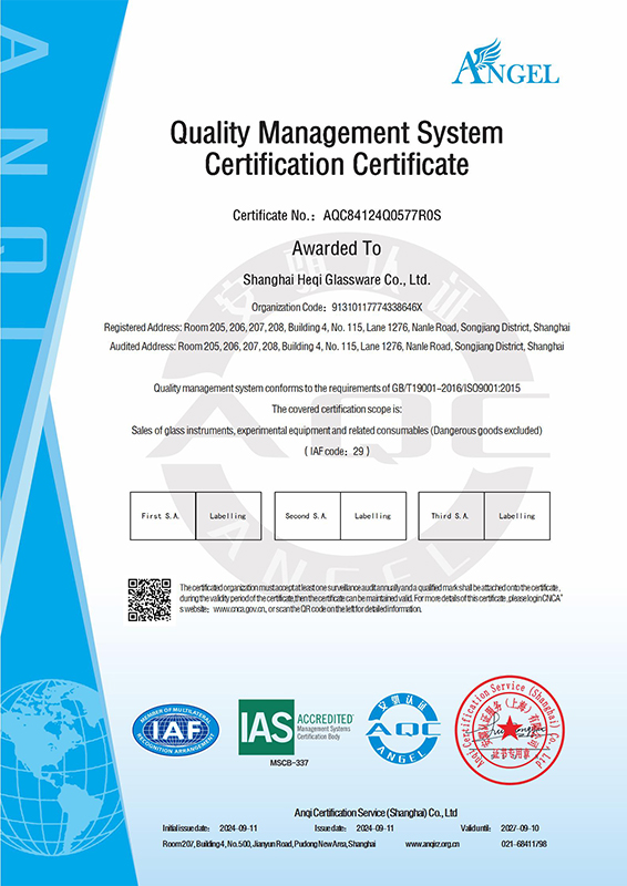
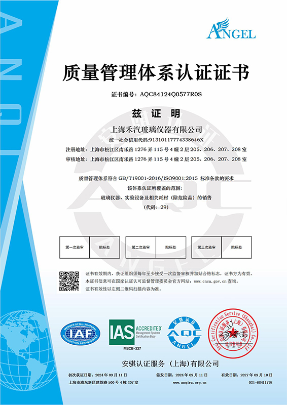
Producing chemical glass equipment capable of enduring demanding laboratory and industrial workflows requires advanced manufacturing infrastructure and material controls. Shanghai Heqi Glassware Co., Ltd. brings extensive technical expertise to the production of standardized glass instruments. Founded in March 2002, the company operates as a prominent China Laboratory Condensers Manufacturers and Laboratory Condensers Factory. Over the years, the enterprise has established modern production bases across key industrial regions including Songjiang, Chengdu, Jiaxing, and Yancheng. By integrating mechanical engineering, specialized glass craftsmanship, and modern management practices, the company transitioned from traditional manual glassblowing to mechanized and semimechanized industrial production lines, significantly reducing unit costs while enhancing dimensional precision and structural consistency.
Quality control in glass condenser manufacturing centers on maintaining uniform wall thickness and eliminating internal mechanical stress induced during hot forming. Shanghai Heqi Glassware Co., Ltd. utilizes automated glass lathe machinery and computer controlled annealing ovens to ensure that every ground glass joint, side arm, and internal coil meets strict dimensional tolerances. To deliver on its core service commitment of you make a call, we handle the rest, the enterprise complements its manufactured product line by supplying high quality glass instruments, laboratory consumables, and experimental equipment from leading domestic and global brands. Through substantial inventory reserves, rapid distribution logistics, and full technical support, the company serves as a comprehensive operational partner for analytical laboratories, educational institutions, and industrial research centers.
Comparative Analysis of Glass Condenser Geometries in Process Chemistry
To support facility procurement managers and principal chemists in specifying appropriate glassware for synthesis and purification workflows, the following table details the key performance characteristics and practical operational scope of major condenser designs.
|
Condenser Design Type
|
Internal Cooling Geometry
|
Primary Process Application
|
Vapor Flow Resistance
|
Fluid Holdup Volume
|
Recommended Operational Orientation
|
|
Liebig Straight Tube
|
Single cylindrical inner tube surrounded by cooling jacket
|
Simple distillation and solvent recovery
|
Minimal pressure drop
|
Very low liquid retention
|
Inclined downward mounting angle
|
|
Allihn Bulb Style
|
Series of expanded spherical bulbs in center tube
|
Continuous reaction reflux under atmospheric pressure
|
Moderate turbulence creation
|
Low to moderate fluid retention
|
Vertical upright mounting angle
|
|
Graham Coiled Tube
|
Extended internal glass coil surrounded by cooling jacket
|
High efficiency downward distillation of volatile fractions
|
High pressure drop across coil
|
High liquid retention inside spiral
|
Vertical upright mounting angle
|
|
Dimroth Internal Coil
|
Circulating cooling coil positioned inside outer vapor jacket
|
Intensive reflux of low boiling organic solvents
|
Very low resistance around coil
|
Minimal center dripping holdup
|
Vertical upright mounting angle
|
|
Friedrichs Spiral Finger
|
Helical cold finger insert with external jacket channel
|
Cold trap condensations and rapid vacuum distillation
|
Moderate velocity channel restriction
|
Moderate fluid drainage path
|
Vertical upright mounting angle
|
Why Are Precision Engineered Laboratory Condensers Critical for Pilot Scale Distillation and Synthesis?
Scaling chemical reactions from benchtop research to pilot plant production introduces significant physical challenges regarding heat transfer efficiency, mechanical stability, and system safety. As reaction volumes expand from milliliters to tens of liters, the volume to surface area ratio changes dramatically, placing greater demands on secondary heat removal apparatus. Precision engineered Laboratory Condensers serve as critical thermal control barriers in pilot scale synthesis assemblies, ensuring that energetic vapor streams generated by large volume glass reactors or industrial evaporators are fully condensed before reaching vacuum pumps or process exhaust headers.
In pilot scale environments, glass condensers must interface seamlessly with complex support frameworks, electronic temperature sensors, motorized agitators, and liquid dosing systems. A failure in condenser structural integrity or joint sealing can result in dangerous chemical leaks, product contamination, or catastrophic vacuum collapse. Therefore, industrial glass components are fabricated from high purity borosilicate glass three point three, a material characterized by an extremely low coefficient of thermal expansion, high resistance to acid and solvent attack, and exceptional mechanical clarity for physical process observation.
Integrating Custom Glass Components with Pilot Scale Reaction Equipment
Pilot scale chemistry relies on modular equipment configurations that can be rapidly adapted for custom synthesis, solvent stripping, or fractional separation. Large scale glass reaction plants utilize jacketed vessel heads fitted with multi port glass covers that accommodate reflux splitters, liquid addition funnels, phase separators, and heavy duty vertical condensers. When selecting components for these large assemblies, mechanical loading on standard taper joints and spherical flange connections becomes a primary engineering concern. Heavy glass condensers filled with circulating cooling fluid exert significant cantilever forces that must be offset by specialized metal support lattices and stress relieving PTFE couplings.
Customization of glass componentry is frequently required to optimize fluid pathways within unique facility layouts. Standard catalog glassware may not fit existing overhead space constraints or specialized circulation manifold locations. A specialized Laboratory Condensers Manufacturer works directly with process engineers to modify port angles, expand internal coil surface areas, incorporate dual cooling jackets, or integrate localized temperature sensor wells. These tailored adaptations ensure that fluid flow remains unobstructed, pressure drops are minimized across high vacuum distillation trains, and liquid condensate drains cleanly back into process vessels without stagnation.
Material Integrity and Mechanical Fabrication Standards in High Vacuum Systems
Operating chemical distillation processes under reduced pressure alters the boiling behavior of mixtures, enabling the thermal separation of temperature sensitive compounds at lowered operational temperatures. Vacuum distillation places severe physical demands on the structural integrity of glass instruments. Under deep vacuum conditions, any atmospheric pressure imbalance, microscopic surface scratch, or micro fracture within the glass wall can initiate structural stress concentration. Consequently, glass condensers destined for vacuum service undergo rigorous stress analysis using polarized light polariscopes to verify complete strain relief during the post fabrication annealing phase.
Precision ground glass joints represent another critical point of mechanical reliability in vacuum systems. Standard taper joints such as size twenty four forty or size twenty nine thirty two must exhibit near perfect geometric roundness and surface smoothness to maintain leak tight seals without excessive application of joint grease, which can contaminate pure reaction products. Modern industrial glass plants utilize automated CNC grinding equipment to produce uniform frosted joint surfaces that accommodate grease free fluoropolymer sleeves or precision o ring seals. These leak free connections prevent air ingress, maintain stable vacuum depth, and ensure precise temperature control throughout volatile fraction collection.
Advanced R&D and Custom Fabrication from a Dedicated Laboratory Condensers Manufacturer
Complex chemical manufacturing and pharmaceutical development require equipment partners capable of moving beyond simple component distribution to deliver fully integrated process solutions. Shanghai Heqi Glassware Co., Ltd. has expanded its technological capabilities by assembling a specialized R&D team composed of senior specialists in chemical R&D, mechanical design and processing, and electronic control engineering. To support advanced manufacturing and custom equipment fabrication, the company established three specialized industrial workshops dedicated to technical glass blowing, metalworking, and final equipment assembly.
These integrated production facilities manufacture a comprehensive portfolio of small scale and pilot scale equipment, including jacketed glass reactors, rotary evaporators, fractional distillation systems, high and low temperature circulating baths, industrial vacuum pumps, overhead stirrers, and UV analytical instruments. Leveraging its in house capabilities in conceptual design, precision machining, and custom glass component fabrication, Shanghai Heqi Glassware Co., Ltd. continuously upgrades product quality metrics and service delivery standards. By offering direct engineering support and customized equipment designs, the company provides tailored technical solutions for fine chemical companies, pharmaceutical synthesis labs, and advanced research institutes globally.
FAQ:
What are the main criteria for selecting between a Liebig condenser and a Dimroth condenser for continuous organic reflux?
Choosing between a Liebig and a Dimroth condenser for continuous reflux depends primarily on vapor volume, solvent boiling point, and required thermal extraction efficiency. The Liebig condenser features a simple straight inner tube cooled by an outer water jacket. While effective for simple downward distillation of high boiling point liquids, its limited surface area makes it inefficient for vertical reflux where high velocity vapors can easily bypass the cold wall and escape into the atmosphere. The Dimroth condenser contains an internal double spiral coil through which coolant flows, surrounded by the vapor stream in the main body. This geometry presents a substantially larger surface area to the vapor stream and creates internal thermal turbulence. Condensate forms directly on the central coil and drips back into the center of the boiling flask, preventing liquid bridging along the ground glass joint walls. For continuous organic synthesis involving volatile solvents, the Dimroth condenser provides vastly superior heat exchange efficiency and prevents solvent loss far more effectively than a Liebig design.
How does fluid flow direction affect heat transfer performance when connecting cooling water to a glass condenser?
Cooling fluid must always enter the lowest connection port of a glass condenser and exit from the highest connection port. This bottom to top flow orientation ensures that the cooling jacket remains completely filled with fluid at all times, purging trapped air bubbles that would otherwise create uncooled hotspots on the glass surface. Furthermore, bottom to top fluid routing establishes a countercurrent heat exchange profile relative to the downward flow of condensate and the upward movement of hot vapor. As hot vapor ascends through the apparatus, it meets progressively cooler jacket temperatures, maintaining a steady thermal gradient across the entire length of the instrument. Connecting fluid hoses in reverse, with coolant entering from the top, causes fluid to cascade quickly down the jacket under gravity without filling the entire volume, drastically reducing cooling efficiency and risking thermal shock to the glass structure.
What preventative maintenance practices protect glass condensers from thermal shock and internal scaling?
Extending the operational life of glass condensers requires systematic attention to temperature limits, fluid purity, and physical handling. Thermal shock occurs when glass experiences rapid localized temperature shifts beyond its material tolerance. To prevent thermal cracking, operators should never introduce ice cold coolant into a dry condenser that is already exposed to hot vapor, nor should they apply high temperature steam to a cold glass body. Coolant flow must be initiated prior to heating the reaction flask. Additionally, hard water used in open loop cooling systems can deposit calcium and mineral scale inside the narrow cooling jacket, reducing heat transfer efficiency and restricting fluid flow over time. Washing internal jackets periodically with a mild dilute acid solution dissolves mineral deposits without damaging the borosilicate glass matrix. Flush the jacket thoroughly with distilled water following acid cleaning to remove residual ions.
What are the mechanical advantages of borosilicate glass three point three in manufacturing pilot scale distillation glassware?
Borosilicate glass three point three is the industry standard material for pilot scale chemical apparatus due to its exceptional chemical resistance, high thermal endurance, and mechanical stability. This glass formulation contains high proportions of silica and boron trioxide, resulting in an extraordinarily low coefficient of thermal expansion of approximately three point three times ten to the negative sixth power per Kelvin. This minimal expansion behavior allows large scale glass components to endure severe temperature swings without developing internal thermal stress. Chemically, borosilicate glass is virtually inert to water, neutral salt solutions, organic solvents, and strong acids, with the exception of hydrofluoric acid, concentrated phosphoric acid at elevated temperatures, and strong caustic alkalis. Its optical transparency allows process chemists to visually monitor liquid film formation, color changes, boiling vigor, and phase separation inside the apparatus in real time.
How do custom ground glass joint sizes and glass flange connections support leak free vacuum operation?
Maintaining deep vacuum conditions in chemical separation equipment requires precise geometric tolerances at all glass connection interfaces. Standard taper ground glass joints rely on a precise one to ten taper angle that creates a tight interference fit when mated. In vacuum applications, precision CNC ground joint surfaces ensure uniform contact across the entire ground area, preventing micro channels through which atmospheric air can leak into the process space. For larger pilot scale condensers where joint diameters exceed fifty millimeters, flat or spherical glass flanges with fluoropolymer gaskets and quick release stainless steel clamps replace standard taper joints. Flange connections distribute mechanical clamping force evenly around the perimeter of the glass interface, preventing stress cracking caused by joint binding while providing superior vacuum sealing under heavy structural loads.
What factors determine the maximum vapor handling capacity of a glass condenser before column flooding occurs?
Maximum vapor capacity is determined by the internal cross sectional area of the vapor pathway, the surface area of the cooling boundary, the temperature differential between vapor and coolant, and the fluid drainage rate of the condensate. Column flooding occurs when the volume of ascending vapor generates sufficient kinetic force to block the downward gravitational flow of liquid condensate, causing liquid to accumulate inside the condenser body. To avoid flooding, facility engineers must calculate expected vapor generation rates based on heating mantle power input and solvent enthalpy of vaporization. If vapor generation exceeds the hydraulic drainage capacity of a given joint or coil design, operators must transition to a larger joint size, switch to a lower resistance internal geometry such as a Dimroth design, or reduce thermal energy input to the reboiler flask.


 English
 Français
 Español